EDGE Curriculum Parametric Design PDF
Parametric design (PD) uses algorithms and mathematical equations to create and manipulate digital models (source). In parametric design, the key parameters of a design, such as size, shape, and orientation, are defined and quantified, and their relationships can be defined by mathematical formulas or rules, rather than by static dimensions or measurements. This allows designers to create complex and highly customizable designs that can be easily modified and adapted to meet different needs or specifications.
The origins of parametric design can be traced back to the development of computer-aided design (CAD) technologies in the 1960s and 1970s. As CAD systems became more advanced, designers began to explore new ways of using computers to create and manipulate digital models. In the 1980s and 1990s, researchers and practitioners in fields such as architecture, engineering, and product design began to develop new tools and techniques for parametric modeling, which allowed them to create complex and highly customizable designs that could be easily modified and adapted to meet different needs or specifications.
However, parametric design differs greatly from traditional 3D modeling and, of course, 2D CAD. It’s based on set rules and parameters, according to which the design is then generated, managed, and modified. Parametric design has significant benefits that improve the design process and ensure that the ready design is of excellent quality.
Today, parametric design is an essential part of many design disciplines, and it continues to evolve and expand as new technologies and approaches are developed. The growing use of parametric design reflects a broader trend towards greater customization, flexibility, and efficiency in design processes, as well as a recognition of the potential of digital technologies to transform the way we create and interact with the built environment.
The following sections will take you through the entire engineering design process again – this time in parametric design.
2.1 PD: Problem Definition
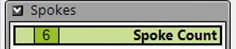
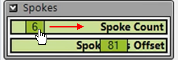
Imagine you are creating a CAD model of a car wheel design with six spokes. How would you model each spoke? You can always create a model of a single spoke, make six copies, and manually rotate each spoke based on your calculations. But what if you could drag a slider called “spoke count” to “6” and see the design being generated right in front of you?
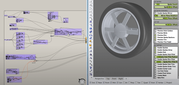
When a designer approaches a problem in Parametric Design (PD), they may still identify the same objectives and constraints. However, they also create a parametric schema (Figure 7) that models the relationships between variables (e.g., the angle between two spokes). This allows them to harness the computational power of modern design software, generate new designs in split seconds simply by entering different values and combinations, and explore a multidimensional design space more systematically and efficiently.

Figure 7. Parametric design of a car wheel frame in Grasshopper. In addition to identifying the same design variables (e.g., number of spokes, width of spokes), the designer also creates a parametric model / schema that models the relationships between variables. (e.g., the blocks and lines on the left), so they can change the number of spokes in the design simply by dragging a slider (top right).
To achieve this, the designer must define the design variables not just as vague descriptions, but rather as quantitative and computable parameters with specific ranges. The software will gladly solve equations for you, but it struggles with reading comprehension. The next practice example will give you an opportunity to define a design variable yourself.
Practice Example 2.1: Parametric Solar Farm Design
Click here to view this practice example.
2.2 PD: Exploration
As a designer, having 2-3 designs is great, but having 20-30 designs is even better. For example, what if you want to compare designs with not just 6 spokes, but also 7, 8, … 20 spokes? Do you repeat the same design process 14 more times
…or would you rather drag a “spoke count” slider to generate each design automatically?
In this stage, designers use parametric modeling tools (Figure 8a) to generate and evaluate multiple design options or alternatives (Figure 8b). This may involve creating digital prototypes, testing different combinations of design parameters, and exploring different scenarios or use cases.
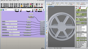
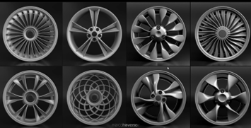
Figure 8. (a) Example of a wheel frame design in Grasshopper to show the Exploration in PD. These methods begin from a basic model and allow the designer to explore different design possibilities by changing the parameters using sliders and then visually representing the changes to the model. (b) A selection of parametrically designed car wheels.
Practice Problem 2.2: Parametric Solar Farm Design
Click here to view this practice example.
2.3 PD: Evaluation
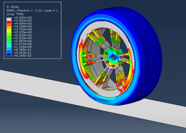
At first sight, the evaluation stage in PD looks similar: Designers evaluate the performance, feasibility, and suitability of the design options that were generated in the exploration stage. However, with the ability to create dozens (if not hundreds) of designs quickly in PD, designers can now evaluate and compare more designs, increasing their chance of finding the optimal design solution or important information that can be used in future iterations.
Practice Problem 2.3: Parametric Solar Farm Design
Click here to view this practice example.
2.4 PD: Iteration
Imagine you have evaluated your car wheel design and want to make a couple changes. Maybe you want to add 2 spokes, reduce their width by 5%, and switch to a different material. Would you start from scratch, or would you rather change some numbers and drag some sliders?
In this stage, designers refine and improve the selected designs by adjusting design parameters (Figure 9) through a series of iterative steps. This may involve incorporating feedback and insights from testing and evaluation into the design, making adjustments or modifications to address any issues or concerns, and then repeating the process until a satisfactory solution is reached. The goal is to create a final design that meets all of the project requirements and that has been optimized for performance, efficiency, and user experience.
Practice Problem 2.4: Parametric Solar Farm Design
Click here to view this practice example.
